banner


Note 9 Camera Glass Cracked

Introduction

Follow this guide to supercede the rear photographic camera of a Samsung Galaxy Note9.

  1. Insert a SIM card eject tool straight into the hole in the SIM card tray. Press to eject the SIM card tray.

    • Insert a SIM card eject tool straight into the pigsty in the SIM card tray.

    • Press to eject the SIM carte tray.

  2. Remove the SIM card tray.

    • Remove the SIM card tray.

    • The SIM card will fall out of the tray easily.

  3. Power off your phone before beginning disassembly.

    • Ability off your phone earlier beginning disassembly.

    • Apply a hairdryer, a heatgun, or prepare an iOpener and utilise it to the right border of the back of the telephone for about a infinitesimal to soften the adhesive underneath.

  4. Apply a suction handle to the back cover. Lift with a suction handle to create a gap between the back cover and the frame of the phone. Insert an opening pick into the gap.

    • Apply a suction handle to the dorsum encompass.

    • Lift with a suction handle to create a gap between the back cover and the frame of the phone.

    • Insert an opening pick into the gap.

    • If the glass is desperately cracked, comprehend it in packing tape to create a surface for the suction cup to adhere to.

    • If the agglutinative won't budge, employ more than estrus, not excessive force. Too much force could break the glass.

  5. Note that there is more adhesive along the top edge and around the camera bezel than around the rest of the phone.

    • Note that there is more than adhesive along the top edge and around the photographic camera bezel than around the rest of the phone.

    • Cut carefully around the left border near the fingerprint sensor or you lot risk damaging the ribbon cable inside.

  6. Starting from the center, cut the adhesive up and down the right side with an opening pick. Do not insert the pick more than halfway into the phone when cutting near the fingerprint sensor or cameras, or you risk damaging internal components. Do not insert the pick more than halfway into the phone when cutting near the fingerprint sensor or cameras, or you risk damaging internal components.

    • Starting from the middle, cut the adhesive upwards and down the right side with an opening pick.

    • Practice not insert the pick more than than halfway into the telephone when cutting nearly the fingerprint sensor or cameras, or you risk damaging internal components.

  7. Leave an opening pick in the upper-right corner. Use another opening pick to cut the adhesive around the bottom-right corner. Leave that opening pick in the phone.

    • Leave an opening option in the upper-correct corner.

    • Utilize some other opening option to cutting the adhesive effectually the lesser-right corner.

    • Leave that opening selection in the phone.

    • Apply an iOpener, hair dryer, or heat gun to utilise more than oestrus equally needed where y'all are cutting the adhesive.

  8. Use a heat gun or hair dryer or apply a heated iOpener to the left side of the rear panel for about a minute to soften the adhesive underneath.

    • Apply a oestrus gun or pilus dryer or apply a heated iOpener to the left side of the rear panel for about a minute to soften the adhesive underneath.

  9. Insert an opening pick into the lower-left corner of the rear panel. Using another opening pick, cut the adhesive along the left edge of the rear panel. Do not insert an opening pick in more than half way on the left edge near the fingerprint sensor or you may damage the ribbon cable inside.

    • Insert an opening pick into the lower-left corner of the rear console.

    • Using some other opening selection, cut the agglutinative forth the left border of the rear panel.

    • Exercise not insert an opening pick in more than half way on the left edge near the fingerprint sensor or you may harm the ribbon cablevision inside.

    • It is fine if opening picks autumn out as the dorsum cover becomes separated.

  10. Using the inserted opening pick, carefully cut the adhesive around the upper-left corner of the rear panel. Finally, cut the last of the adhesive along the top of the phone. Use an iOpener, hair dryer, or heat gun to apply more heat as needed where you are cutting the adhesive.

    • Using the inserted opening selection, carefully cut the agglutinative around the upper-left corner of the rear panel.

    • Finally, cut the terminal of the agglutinative forth the acme of the phone.

    • Utilize an iOpener, hair dryer, or oestrus gun to apply more heat every bit needed where yous are cutting the adhesive.

  11. Separate the right side of the rear cover first. Tilt the cover up along the left edge to expose the fingerprint sensor ribbon cable.

    • Divide the right side of the rear cover offset.

    • Tilt the comprehend up along the left edge to betrayal the fingerprint sensor ribbon cable.

    • Exercise not pull out the fingerprint sensor ribbon cable yet.

  12. Use the tip of a spudger to pry the fingerprint sensor ribbon cable up and out of its socket. Use the tip of a spudger to pry the fingerprint sensor ribbon cable up and out of its socket.

    • Use the tip of a spudger to pry the fingerprint sensor ribbon cable up and out of its socket.

  13. Remove the back cover.

    • Remove the back cover.

    • To install a dorsum encompass:

    • Use tweezers to peel abroad any remaining adhesive from the phone'south chassis. And then clean the adhesion areas with high concentration isopropyl alcohol (at least 90%) and a lint-free cloth to prep the surface for the new adhesive.

    • Plow on your telephone and examination your repair before installing new adhesive and resealing the phone.

    • Carefully apply the new adhesive to the back cover, so line up one edge of the glass against the telephone chassis and firmly printing the glass into the phone.

    • Alternatively, you may reinstall the back comprehend without replacing the adhesive. Remove any large chunks of adhesive that might preclude the back embrace from sitting downwards flush. Subsequently installation, heat the back cover and apply force per unit area to secure it. It won't be waterproof, but the glue is commonly more than potent enough to hold.

  14. Use a Phillips screwdriver to remove the nine 4 mm screws securing the upper midframe. Use a Phillips screwdriver to remove the nine 4 mm screws securing the upper midframe.

    • Use a Phillips screwdriver to remove the nine iv mm screws securing the upper midframe.

  15. Insert the tip of a spudger into the upper-left corner of the upper midframe. Pry the upper midframe out of the phone.

    • Insert the tip of a spudger into the upper-left corner of the upper midframe.

    • Pry the upper midframe out of the phone.

    • The upper midframe snaps into and out of place.

  16. Peel the wireless charging coil off the battery starting with the left side. The adhesive is weak but you can use an opening pick to cut it if necessary. During reassembly start by snapping the midframe into place first before adhering the wireless charging coil.

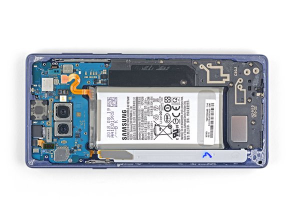
    • Peel the wireless charging scroll off the battery starting with the left side.

    • The adhesive is weak but you tin can utilise an opening pick to cut it if necessary.

    • During reassembly get-go past snapping the midframe into place first before adhering the wireless charging roll.

  17. Use the tip of a spudger to disconnect the orange ribbon cable connecting the battery to the motherboard. Use the tip of a spudger to disconnect the orange ribbon cable connecting the battery to the motherboard.

    • Use the tip of a spudger to disconnect the orangish ribbon cable connecting the battery to the motherboard.

  18. Remove the nine 4 mm Phillips screws from the plastic cover next to the battery. Remove the nine 4 mm Phillips screws from the plastic cover next to the battery.

    • Remove the 9 4 mm Phillips screws from the plastic cover next to the battery.

  19. Remove the plastic cover next to the battery.

    • Remove the plastic encompass next to the battery.

  20. Insert the tip of a spudger into the top of the lower midframe. Pry the lower midframe out from the phone. The lower midframe snaps into and out of place.

    • Insert the tip of a spudger into the acme of the lower midframe.

    • Pry the lower midframe out from the phone.

    • The lower midframe snaps into and out of place.

    • Remove the lower midframe.

  21. Use the tip of a spudger to pry the front camera connector straight up and out of its socket. Use tweezers to remove the front camera. Use tweezers to remove the front camera.

    • Utilise the tip of a spudger to pry the front photographic camera connector direct up and out of its socket.

    • Use tweezers to remove the forepart camera.

  22. Use the tip of a spudger to disconnect the iris scanner from the motherboard. Use tweezers to remove the iris scanner. Use tweezers to remove the iris scanner.

    • Apply the tip of a spudger to disconnect the iris scanner from the motherboard.

    • Utilise tweezers to remove the iris scanner.

  23. Use the flat end of a spudger to pry the front sensor connector out of its socket. Use the flat end of a spudger to pry the front sensor connector out of its socket.

    • Use the flat finish of a spudger to pry the front sensor connector out of its socket.

  24. Use the flat end of a spudger to disconnect the display cable from the motherboard. Use the flat end of a spudger to disconnect the display cable from the motherboard.

    • Use the flat finish of a spudger to disconnect the brandish cable from the motherboard.

  25. Use the flat end of a spudger to disconnect the touchscreen cable from the motherboard. Use the flat end of a spudger to disconnect the touchscreen cable from the motherboard.

    • Utilise the flat end of a spudger to disconnect the touchscreen cable from the motherboard.

  26. Use the flat end of a spudger to disconnect the charging assembly from the motherboard. Use the flat end of a spudger to disconnect the charging assembly from the motherboard.

    • Utilise the flat cease of a spudger to disconnect the charging assembly from the motherboard.

  27. Remove the three 4 mm Phillips screws securing the motherboard. There are triangles next to the holes indicating the motherboard screw locations.

    • Remove the three iv mm Phillips screws securing the motherboard.

    • At that place are triangles next to the holes indicating the motherboard screw locations.

  28. Use a spudger to gently lift the motherbord from the upper-left corner. Carefully remove the motherboard. Move the ribbon cables out of the way as necessary. Do not pull the motherboard out if it becomes snagged on any cables.

    • Use a spudger to gently lift the motherbord from the upper-left corner.

    • Advisedly remove the motherboard.

    • Motility the ribbon cables out of the way as necessary. Practice not pull the motherboard out if it becomes snagged on whatsoever cables.

  29. Use the tip of a spudger to pry the rear camera connector straight up and out from the motherboard. Use the tip of a spudger to pry the rear camera connector straight up and out from the motherboard.

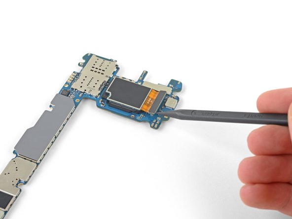
    • Utilize the tip of a spudger to pry the rear camera connector straight up and out from the motherboard.

  30. Use a heat gun or hair dryer or apply a heated iOpener for about a minute to soften the adhesive around the rear camera.

    • Use a heat gun or hair dryer or apply a heated iOpener for nigh a minute to soften the adhesive around the rear camera.

  31. Carefully pick up the motherboard. Using your thumbnails, press on the metal bezels to separate the rear camera from the motherboard.

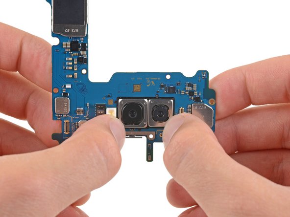
    • Advisedly pick up the motherboard.

    • Using your thumbnails, printing on the metal bezels to separate the rear camera from the motherboard.

    • Practise not printing on the lenses themselves if you don't want to damage the rear camera.

    • Stop once you experience the rear camera begin to divide from the motherboard. You don't need to press it entirely out all the same.

  32. Insert the flat end of a spudger into the gap between the rear camera and the motherboard. Lift to separate the rear camera from the motherboard.

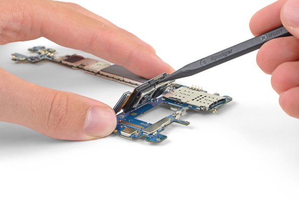
    • Insert the apartment cease of a spudger into the gap betwixt the rear camera and the motherboard.

    • Lift to split up the rear photographic camera from the motherboard.

  33. Remove the rear camera from the motherboard.

    • Remove the rear camera from the motherboard.

Conclusion

To reassemble your device, follow the to a higher place steps in reverse society.

Take your e-waste to an R2 or e-Stewards certified recycler.

Repair didn't go every bit planned? Check out our Answers community for troubleshooting aid.

Compare your new replacement office to the original part—you may need to transfer remaining components or remove adhesive backings from the new part before installing.

Team

Embed this guide

Choose a size and copy the code beneath to embed this guide as a pocket-sized widget on your site / forum.

Preview

Source: https://www.ifixit.com/Guide/Samsung+Galaxy+Note9+Rear+Camera+Replacement/136652

0 Response to "Note 9 Camera Glass Cracked"

Post a Comment

Iklan Atas Artikel

Iklan Tengah Artikel 1

Iklan Tengah Artikel 2

Iklan Bawah Artikel